
If you’re working in a substation, the busbar is the heart of your operation. It’s also the one place where a failure doesn’t just trip a feeder; it clears the entire station. When I hear vendors talk about “next-gen, self-healing, AI-integrated busbar protection,” I reach for my multimeter. You don’t need AI. You need Kirchhoff’s Current Law (KCL) implemented with absolute, unwavering rigidity.
The Problem Nobody Talks About
The fundamental challenge with busbar differential protection is that it is the ultimate “all or nothing” scheme. If a line relay trips, you lose a load. If your busbar protection misoperates, you lose the facility.
 Image Credit: elprocus.com
I once walked into a 230kV substation after a “phantom” trip. The protection engineers were blaming a transient disturbance on the grid, but the logs showed something far more mundane: a secondary circuit saturation issue during an external through-fault. Because the CTs (Current Transformers) on one of the feeders were mismatched—a 2000:5 and a 3000:5 sharing the same differential zone—the secondary currents didn’t balance during a heavy external fault. The differential relay saw a massive “leakage” current, panicked, and dumped the bus. The plant was dark for six hours because someone decided to save a few bucks on matching CT ratios.
Technical Deep-Dive
At its core, a busbar differential scheme is a simple summation of currents: $I_{diff} = \sum I_{in} - \sum I_{out}$. Under normal conditions, $I_{diff}$ should be zero. When you have an internal fault, $I_{diff}$ becomes the total fault current, and you trip.
The nightmare starts with CT Saturation. During a heavy external fault, the DC offset in the fault current can drive your CTs into saturation. If one CT saturates faster than the others, the secondary current drops, the differential current spikes, and you get a nuisance trip.
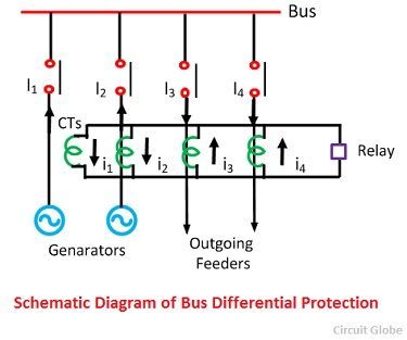 Image Credit: circuitglobe.com
To combat this, we use Percentage Differential Protection. Instead of a fixed threshold, we use a slope characteristic. As the through-current (restraining current) increases, the threshold for the differential current (operating current) also increases. This provides the “slack” needed to account for CT errors and minor mismatches.
The Digital Shift
With the move toward substation automation iec 61850, we’ve moved from copper-wired hard-wired schemes to sampled values (SV) over fiber. While this eliminates the copper loop resistance issues, it introduces jitter and latency concerns.
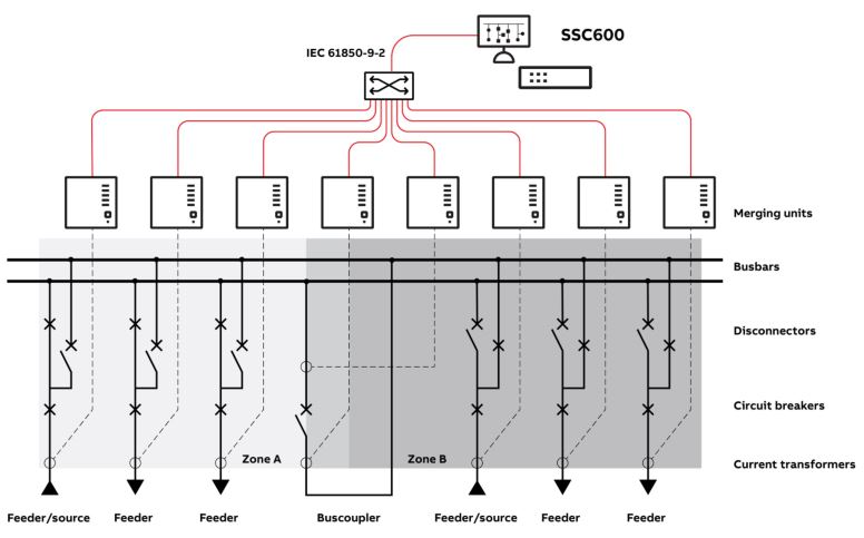 Image Credit: controlecommande.com
graph TD
    A["CT Secondary"] -->|"Analog-to-Digital"| B["Merging Unit"]
    B -->|"IEC 61850-9-2 SV"| C["Busbar Differential Relay"]
    C -->|"GOOSE Trip Command"| D["Circuit Breaker IED"]
    E["External Fault Monitor"] -->|"Restraining Signal"| C
    C -->|"Logic Check"| F["Trip/Block Decision"]
Implementation Guide
When you’re commissioning these, don’t just trust the relay’s internal diagnostics.
- CT Ratio Matching: If you can’t match ratios physically, use auxiliary CTs or software compensation in the relay. If you use software, document it clearly. The next guy who works on this shouldn’t have to reverse-engineer your math.
- Zone Selection: Use a “Check Zone” and “Operate Zone” logic. The Operate Zone is specific to each bus section, while the Check Zone covers the entire station. A trip only occurs if both zones see the fault. This is the only way to prevent a trip caused by a relay failure or a wiring error in a single zone.
- Polarity Check: I don’t care how good your wiring diagram is. Perform a phase-angle test with primary injection. If you don’t have a primary injection set, you aren’t testing; you’re guessing.
| Feature | Low-Impedance | High-Impedance |
|---|---|---|
| CT Requirement | Matched ratios preferred | Identical CTs required |
| Sensitivity | High | Medium |
| Complexity | High (Logic/Settings) | Low (Simple relay) |
| Wiring | Multi-core to Central Relay | Parallel wiring to Resistor |
Failure Modes and How to Avoid Them
The most common failure mode isn’t the relay hardware; it’s the secondary circuit integrity.
- The Open-Circuit CT: If a CT secondary circuit opens, the relay sees a massive differential current. Ensure your terminal blocks have automatic shorting links. If you ever have to lift a wire, short the CT first. No exceptions.
- DC Offset Saturation: If your protection scheme doesn’t have a robust algorithm to handle the decaying DC component of a fault, you will trip on external faults. Ensure your relay has a “DC-offset blocking” feature or a sufficiently high restraint slope.
- The “Human” Factor: I once saw a technician accidentally leave a test switch in the “Test” position after a routine check. The relay was effectively bypassed for three months. Use physical lockout devices or “In-Service” status monitoring via SCADA.
When NOT to Use This Approach
Don’t use complex differential schemes on small, low-voltage distribution buses where a simple overcurrent protection scheme suffices. If the cost of the busbar protection system exceeds 10% of the value of the switchgear it’s protecting, you’re over-engineering.
Furthermore, if your substation is in an area with high seismic activity or extreme temperature swings, avoid complex fiber-optic-based merging units if you don’t have the maintenance staff to handle fiber optic repairs. Sometimes, a copper-based, high-impedance relay is more reliable because it’s simpler and easier to troubleshoot with a standard DMM.
Conclusion
Busbar protection is a game of margins. If you aren’t obsessing over your CT saturation curves, your phase-angle relationships, and your trip-logic redundancy, you’re just waiting for a bad day. Stop looking for “disruptive” tech and start looking for rigorous, proven, and boring engineering. Your grid will thank you for it, even if your marketing department doesn’t.
Hero image: Yellow device mounted on wooden beam with wires.. Generated via GridHacker Engine.


